Week 1-2: Environment Layout/ Scene Organisation
Maya section
This section is a general view of the tasks that I've done in Maya with low polygon assets. I'll go through with my understanding and description of these features.
.png)
Grouping
In a very messy outliner tab, it's important to group up objects into a single folder. By selecting the objects you want to group up and press Ctrl + G, You'd be able to do just that. It's a good way of sorting out models.
.png)
Layers
A bit similar to grouping, but on another tab and including new features. On Channel-Box/Display the user can create a layer out of the selected models and have the option to edit their display.
.png)
Custom Pivot
The Pivot is a centre point where it allows the user to move, rotate and scale a selected object from that point. This is useful for moving a tip of a model or the bottom of this tree in the picture.
If the user wants to change the pivot's direction, they can press D and change the pivot into what it looks like on the screen. This allows to edit the positioning and rotation of the pivot once the user presses D again to save changes.
You can also hold Ctrl to move the pivot to a specific vertex or the general area of said vertex when holding one of the arrow directions.
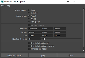
Duplicate Special
With this tool, I'm able to duplicate a model in a signle press of a button and a few directions. On the Options tab, there are setting to tell the tool where to duplicate the object in what direction, what rotation and what size. Add to that, the user can choose how many duplicates can occur at once.
.png)
.png)
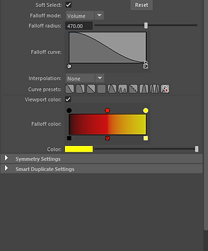
Soft Selection
When double clicking the move/rotate/scale tool, a window opens to reveal a tool called Soft Select. Basically, when selecting vertexes or edges, it creates a faded range around it depending on the chosen colour. when the vertex is moved, the other ones drag along with it. As shown in these pictures, it's used to make hills and holes.
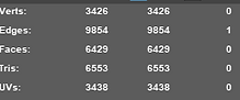
Poly Count Display
In Display and Heads Up Display, you have the option to view your polygon, edge and vertex count on the top corner. It shows the total on the start and the selected object's amount on the other side.
.png)
.png)
.png)
.png)
Sculpt Tools
With a Plane containing a couple hundred subdivisions, Maya has the ability to sculpt bumpy structures like the ones on the right picture. It all depends on the strength and the size of the brush, even what direction it goes from up or down.
The other sculpting tools are the Smooth tool that smooths out sharp edges like the left mountain, while the Grab tool allows the user to grab a portion of the plane and make structures like the ones on the back left area.
.png)
.png)
.png)
Sculpt Stamps
One of the features to the basic sculpt brush is the Stamp tool which allows for custom brushes or stamped hills to appear. This is done with getting a black and white image that looks like the one below. I took this one from a map of the world that highlights mountains white.
Once equipped and checking the box, the user can now paint over the Plane with this brush. Or if all the plane needs is just the image like in the box, then you can go to the Draw method and choose Scale image from Centre. Click and hold onto the plane, rotate the flat image to the desired direction and let go to press the image to the plane.
.png)
Week 3 - Environment modelling/ Texturing
Importing Alpha textures
The following tasks involve making a tree out of a cylinder and a few dozen panes that contain branches of leaves with a transparent background. How alphas normally work is that they're the transparent part of a texture, which occur in PNG images that come with it.
This branch already comes with a transparent background and the file is connected to the Transparency part of the material.
Editing Plane
With the branch texture in place, I edit the vertexes of this 2X2 plane to give the branches more depth for when they're placed on the cylinder. I also edited the pivot position carefully so it's on the beginning part of the branch.
.png)
.png)

Duplicating branches
I went along and placed down a cylinder with a brown lambert material. Next, I carefully placed the branch into the cylinder and duplicated them one at a time. DUplicate special didn't work that well as most of the branches flew off or lost their edited pivot when duped so I had to do it manually.
Each row has 4 planes to which I then slightly rotate to a different position and slightly shrink per row to make it seem more like a tree.
Extruding Tree
For this section, I'd need to make a tree out of a simple cylinder and extrude new branches in mulitple extrude techniques.
The simple ones are just clicking on a face and pressing Ctrl + E. Then dragging the face and repeating the process.
Another quick one is simply holding Shift while the face is dragged.
A much more complex extrude involves drawing a line like in the image, selecting the face of the trunk and line, and then extruding it. It looks
.png)
weird at first, but the extrude needs its subdivision to increase in order to have more polygons bend the branch in it's desired shape.
.png)
Extruding continues
I continued to extrude the branches with the line method and manually and once I was happy with my results, I moved onto the roots on the bottom. It felt like there needed to be some more detain so I did manual extruding for this one. I even attempted to make one go over another root for some extra detail.
While this happened, I messed with the edges of the trunk to make small bumps.
.png)
Conclusion
After smoothing out the tree, this was the final result and alongside that, below is what the previous tree looks like in it's entirity.
_edited.jpg)
Week 4: Realtime and Pre-rendered Lighting
Lighting setup
This setup was made with a curved plane and in the centre of it is a 3D object of my choice. I decided to go with the horse head for the demonstrations. I also have a camera set to 1920 X 1080 for the Arnold Renderer.
Another thing to note is that Maya sometimes doesn't have file formats accessible for Imports and Exports, so they need to be manually ticked in. The list is found in the Plug-in Manager.
.png)
.png)
.png)
.png)
Arnold Area Light
This object comes with the Arnold renderer and it's basically a square with a cross and a line inbetween. The line points to the direction of the light and there's customizations for the colour, intensity, spread and the shape of the Area Light.
Light Blocker
In the Area Light settings, there is an option to add another object connected to the Area Light, and it's called a Light Blocker. It's simply any outlined shape the user picks for it and is used to block light depending on it's position.
Examples
Below are 3 low res images of Arnold renders that are only meant for demonstrations. The first one is only the Area Light with heavy exposure and large spread. The spread has the light expand around the horse but lose it's brightness.
The second picture shows a sharper light with no soft edges, no spread and a little less exposure for correctness. This technique completely blacks out any other part of the horse that isn't pointed at by the Area Light.
The third one involves the Light Blocker placed over the horse's eyes. The current version was a square pane but there are other shapes like cubes.
.png)
.png)
.png)
In the end, I decided to combine all that I've learned and made this higher quality Arnold render of the horeshead with the Area Light and the light blocker.

This right here is a Unity scene given to me for the purpose of briefly demonstrating the lighting in Unity.
.png)
The directional light is what controls the sun in the Unity scenes, which in turn creates sunsets and different shadow directions depending on where the lines are pointing.
.png)
.png)
Spot Light is more of an actual spotlight that points an outline of a cone to it's general direction. When in contact with the inside of a cone, a circle of light shines on the object and casts a shadow to props or this skeleton.
Week 5: Creature Modelling/ Detailing
This week, I'll be dipping my toes in ZBrush which is a software designed for sculpting 3D models and such. My first task is to get to work on sorting out a tree model and creating a UV map that works.
The tree and UV
Since making UV maps is a very time consuming task, I went along with making a rougher tree than reusing my more complex one. This one uses basic extrution for thebranches and trunk and then I begin by opening UV.
.png)
.png)
UV Cutting
I plan on separating the branches and trunk into their own UV Shell and freely move around the unfolded shell. I selected the edges that I need to cut (IE: The trunk's one line down and around the branches) and then select the Cut tool to make the white line.
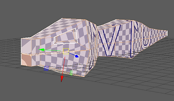
Mapping
Since this tree used to be a cube, the UV needs a remapping. So I selected the Shell I wanted to remap and then pick the cylindrical mapping tool since it's perfect at wrapping around the trunk. Then, I used the unfolding tool to split it open and resized it so the checkered textures looked right.
.png)
.png)
Due to difficulties and tight schedule, I wasn't able to map out the branches in a proper method and had to rely on a pre-mapped tree for ZBrush.
ZBrush Beginning
This software is bizzare from the getgo. Firstly, to import a model, you have to pick it and then drag a mouse to resize and rotate the object. Then switching to the edit mode, I'm able to change textures, reorient the model properly and start onto the Normal mapping.
ZBrush Normal Stamp
Similar sounding to the Maya stamp tool, but it's different. This tool paints over a 3D model with a stamp that's meant for the normal map texture for the model. Normal is essentially making these small bumps in the model using a blue and purple coloured map. These are usually used for bricks, rough textures and wood bark, which I'm trying to apply.
I download a bark stamp, import it here and use the brush to paint the stamp on the model. It is possible to move the stamp freely, but since I'm fresh meat on this software, there's too much stuff I need to be aware of.
My only focus for now is the trunk and one branch as this is only demonstration of the tool.
.png)
.png)
Final results
I imported the Normal map as a PNG from ZBrush to the current Maya texture and from the looks of things it does work, but the branches are conflicting with shadows and clippings. Perhaps it's a model issue.
.png)
.png)
Extrution returns
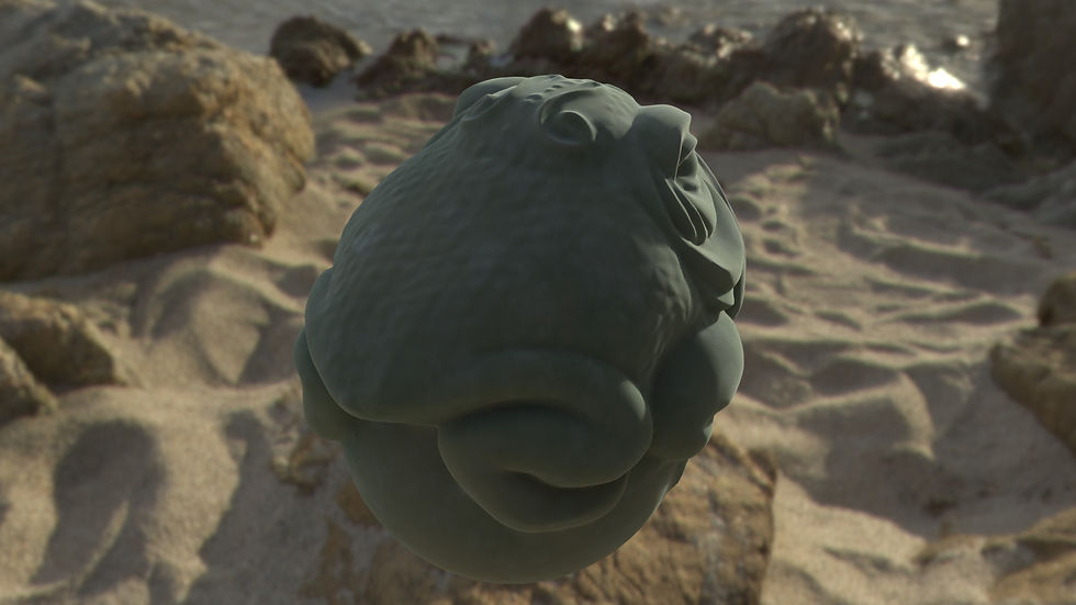
Extruding makes a return as I use it to create holes for eyes, mouth and extend the head and tail further.
Smoothing
Once I'm happy with the design, I smooth it out with the smooth tool and add more polygons for ZBrush.
The next task is to make a lizard, or at least the body and head of a lizard, sort out the UV and make a Normal map in ZBrush with it.
Modeling the body with symmetry.
I began with a cube with 2x2x4 Divisions and using a Symmetrical tool. This allows me to edit one side of the model and it mirrors the other side. I have used this technique before with a shoe. This is helpful in this scenario as I'm trying to make an accurate looking lizard.
.png)
UV Mapping
Instead of using the cylindrical option, I went with a Planar mapping which involved using a flat plane to map out the lizard. Once I've done that, I would jump ahead into cuting out the tip of the tail, eye and inside of the mouth to make it easier for the body to unfold. Once done, I can confirm that the results came out well. I repositioned the eye, mouth and tail tip Shells and it's near perfect. All except for the nose, but I couldn't find a way of flattening that nose
Why the half?
Since this is a symmetrical 3D model, I only need to focus on the one side of the reptile and then apply the other half once I'm done with the first.

.png)
Week 8: Substance Painter

.png)
2048
.png)
.png)
.png)
Substance painter is a texturing tool for 3D models and since then, I've used it for this and other modules. This week and the following ones will go through my understanding of the program. I'll begin with texturing a skull model.
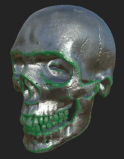
Baking
What's happening here is I'm baking the Skull mesh to gain more information for texturing the 3D model. This is to help me out with the curves and edges for a couple of my tasks that I'll be documenting below. Without this bake, then my skull would have troubles with understanding the mesh and result in worse looking textures.
For this demonstration, I chose select all bake options and change the output size to 2048 for higher quality. Once I've began baking, the program automatically bakes the mesh and creates more maps on the side of the screen.
Layer Materials
To start things off, I add 2 layers. The first one is an iron material from the materials list. It's easily applied by dragging the material into the mesh with the mouse.
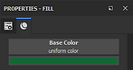
The second layer is a fill layer that applies a single colour over the mesh. I get this layer by pressing the paint bucket tool in the Layers tab. I decided to go with green for this model.
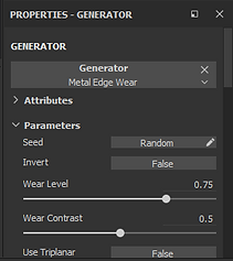
Generator
With the help of the previous step where I baked my model, I can use an edge generator to change the appearance of the green texture more neatly. Before we use a generator, I made a mask for the fill layer and applied a Metal Edge Wear generator. The purpose of this is to cut out the black parts of the mask and leave the white parts of the mask visible. Outside of the mask layer, The green parts where the white stays on the model while everything on black is removed.
The Generator I went with drew a white mask around the texture to highlight the edges and can be edited in the properties tab. To reverse the mask, you can right-click on the model and press Invert Mask so that the edges are cut off and the middle stays.
Future Note: During the following weeks, I wasn't aware to keep the inverted mask on the skull and went with the left skull instead. This continued till Week 10. This is just to clarify any confusion as to why my skull looks the way it does in the future.
.png)
.png)
.png)
.png)
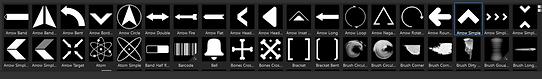
Stamping
With an empty layer and a paint tool, you can paint on the model itself, as well as use prefab shapes to stamp. By changing the desired colour and turn the height level down, I can click on wherever I want to make a cut pattern on the mesh. On the right, it shows an example of the decor that I did on the skull. On another layer, I also decided to make a smudged handprint to see the results of that.
.png)
.png)
.png)
Display Settings
With the display settings, I'm able to change the lighting and the background using either built-in backgrounds from the Substance Painter folder or gather some online. This will be important for rendering out the skull in iRay renderer. By default, the opacity is 0 so it needs to be turned up in order to see the background. There are also other tools like rotation for when the background needs to be the right way and the blur depending on how obscructed or clear the background is.
.png)
iRay Renderer
Similar to Maya's Arnold renderer, iRay is used to make high quality renders with settings to its resolution, how much it wants to render and for how long. The iRay renderer i. The results from the iRay can be displayed on the bottom gallery.


Week 9: Shader setup
.png)
.png)
.png)
This week revolves around importing textures and meshes from Substance Painter and into Autodesk Maya, and then into Maya's Arnold renderer.
Import and Export
For the model and texture, I went with the Jade frog from the Substance Painter's prefabs. I began by exporting the model as an OBJ which is an easy format for Maya to import. For the textures, I exported them as 2K (2048) PNGs and took the following 5 maps: BaseColour, Metalness, Roughness, Height, and Normal.
Once I've opened a new Maya folder, I imported the frog and created a new material called AiSTandardSurface. This material is commmonly used for Arnold rendering and so I'll use it primarily on the Jade frog. The base material applied would be the BaseColour and the rest will be added in their respected places.
Placing textures
Easily, I'm able to open the side tab of the materials menu and apply the existing maps as files. I'd do this to Metalness, Roughness, Height and Normal.
If I was to see a list of everything I added to the material, I'd click on a sphere icon above Maya that takes me to a materials list. There I'm able to change properties of a material by clicking the boxes, moving the connecting lines around, changing the values of the PNGs from RGB to Raw,, or deleting/adding other maps and trextures.
Skydome
Before rendering out the model in Arnold, it needs to have a skydome in the scene. The point of having a Skydome is so that in a way, it acts as a room for the models to create a light source and a photographic background for Arnold. You can download these backgrounds online or make your own (Which I won't). This same background is similar to the one in Substance Painter, but it acts more like an object than a permanent feature.
Arnold Render
With everything in place, I rendered out the model with everything I've got in place and made 2 pictures. The render is similar to the one in Substance Painter, but with fewer options on how long the render goes for and instead has more options on what parts get rendered and how high quality will the image end up.

Week 10: Unity/Unreal setup

Importing things differently
For this setup, I'd have to import Substance Painter to 2 game engines; Unity and Unreal Engine 4. For Unreal, the textures had to be in a TGA file and the mesh in an FBX file, which is also used in Maya.
Unity on the other hand can take on PNG but would need an extra texture map called an Occlusion. This map helps with the shadow and light placements in all lightable areas to tell what shines and what doesn't.
.png)
Unity import
With Unity, I imported the textures and the mesh of the skull by dragging all the material into a folder in the tab on the bottom. Once everything's moved to the project, I dragged the skull to the scene and positioned it so I can see where it faces.
Much like my last lesson with Maya, I need to make new material, so I did. I right-clicked and created a new material. I dragged the icon to the skull in the scene and it's applied to it.
Applying Unity Textures
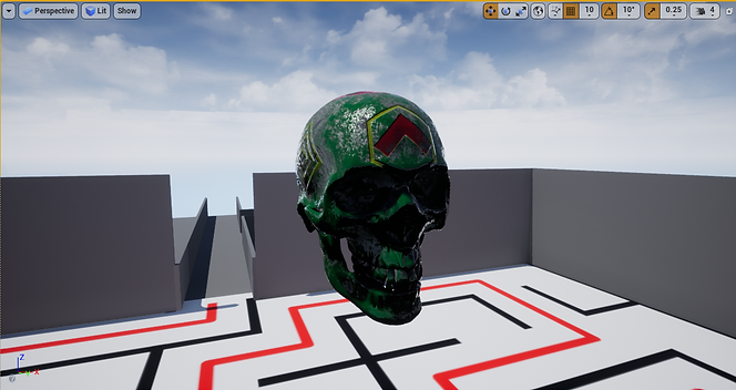
When clicking on the material, the inspector opens a menu for the material. It's also important to place a lock on the inspector for the next step. With my textures ready, I dragged the BaseColour, Metallic, Height, Normal and Occlusion maps to their desired spots on the Inspector. With these textures added, the skull updates with the textures and the normal mapping displaying like in Substance painter.
.png)
This is what the skull looks like in-game.
.png)
.png)
.png)
Unity Background
The backgrounds for Unity like the other programs before them can be changed with the use of the Lighting tab. Before I get to that, I drag the same background files as before and changed their attributes in Inspector; Changing the texture shape to Cube and the mapping into Cylinder.
After that, I add another material and add the object to the material. Then, I open the lighting tab and drag the material to the Skybox Material box and the scene updates itself.
.png)
The background changes are present below.
.png)
.png)
Importing to Unreal
For Unreal, I've taken the fbx and tga files and dragged them into an Unreal tab, similar to Unity and from there, the process is almost the same, apart from editing the textures out.
.png)
Texturing in Unreal.
This system is quite similar to the one in Maya with the boxes and lines, but slightly different in line placements. I spawned about 3 maps in boxes called Texture Sample and dragged the lines in places they need to be in.
Base and Normal maps are placed normally, but the Metallic map splits its RGB values across. Green goes into Roughness, Red goes into Occursion and Blue goes to Metallic.
.png)
.png)
My model wasn't placed in a very bright room, but the textures do work and everything was plugged in the right place.
.png)
My own work
For the following weeks, I've been documenting the tasks that I've been doing for the past weeks. Now, I'm left to my own devices and I'm going to make my own model in Autodesk Maya with UV mapping and render it in Arnold, and then paint it in Substance Painter and import the textures to the model.
What am I making?
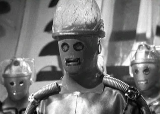
The model that I'll be making is a recreation of the Cyber Controller's helmet from Doctor Who's serial, Tomb of the Cybermen from 1967. The head would be made of a grey metal with chrome eyes and mouth with black outlines around the facial features. In addition, there are speakers on both cheeks and on both sides, an outline that indicates the helmet being more than one piece. One noticable detail would be the large translucent brain dome on his head with veins around it. If it's possible, I might be able to place a light inside the head to make it glow.
Reference
For references to the helmet, I'd need the front and back of the helmet drawn in an outline. Problem is that I couldn't find any outlined work on the Controller and I didn't own a copy of the serial to snag references. Even if I did, all the shots were black and white. However, I was able to utilize a reference from my shelf; A Cyber Controller action figure that I happened to own.
Ignorable Side Note: The Controller figure was part of a action figure set and was split into 4 parts to be sold in separate packages. The head was obtainable through the Tenth Planet Cyberman set.
Due to the nature of the action figure, the helmet was safely detatchable so it prompted me to use that as a reference. I took photos of the side of the helmet and front using my phone, albeit not the best quality since it didn't react well to things up close. I would use these 2 images to help me shape the model. When I'm unsure about the finer details, I still have the action figure's head as personal reference.


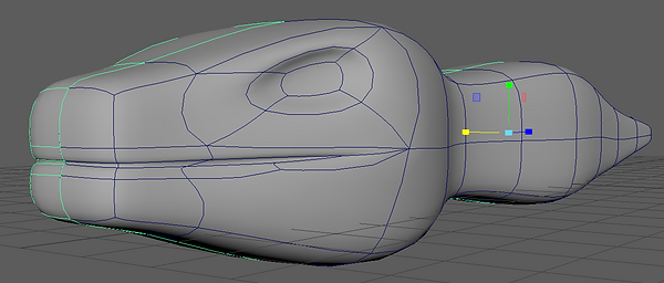
Starting point
I began by creating a cylinder primitive. I change its subdivision values to 20, 10, 1. This is to start off with enough polygons to add it's facial features and have a smoother surface to work on. I imported the 2 images and made extra caution to make sure they were both the same size and the same position. With the help of the grid in the Front and Side cameras of the Maya scene, it made it easy.

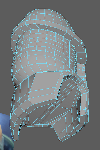
Extruding begins
With everything set, I was going to start the most common task that I'll be doing throught; extruding. I moved the extruded the top of the cylinder, making the metal ring and then extruding more times to make the whole dome shape. Once that was done, I moved to the bottom part of the cylinder and slightly turned the bottom polygons so they looked at the bottom.I then extruded down and shrunk the faces to make a chin. Throught this process, I continue to use the images as reference.

Extruding the back
I moved onto the back where I've extruded the polygons of the original cylinder and pulled them back. From the top of the new shape, I've made a few holes on top of the dome and ring on the back for later. I then extruded the top polygons of the extruded shape up and continued to extrude until I reached the top. With a weld tool, I connected the indexes together to seal the holes I've made.
Final touches involved me stretching the sides of the extruded shape, mostly the bottom parts to get a good shape. I continued to used the head as reference.

Bottom details
And so, I continued to extrude from the bottom section this time to create the shoulder parts. It started off with extruding regular shoulders and then slicing off the sides to leave 2 hollow holes. There wasn't any need for the bottom part so that's deleted too.
After stretching the very edges of the cut area, I extruded them into new polygons and dragged them down and inside the helmet to form a new shape. When I kept extruding the edges to the point of covring most of the hollow area, I used a Fill Hole tool to fill a hole in the centre. To avoid having N-Gons, I cut out new edges on the filled hole to make quad polygons.

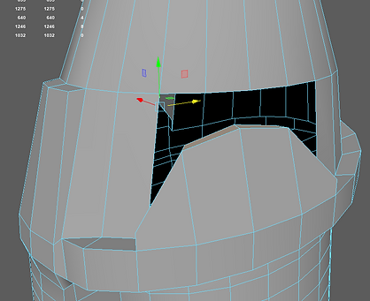
More extruding and welding
Additionally, I wanted to make these curved metal parts on the dome that show up on the side. I extruded about 4 faces in the right area and moved the middle edges slightly to make a curve. Then, I repeat the same process as the object on the back: Deleting the obstructing polygons and weldding the indexes to eachother to cover the hole.
As for the side bumps and eyes, I select 4 to 6 faces and used the Circular tool to round the faces into a perfect circle. For the bumps, I didn't need to extrude since I got a nice curve when pulled. As for the eyes, I extruded them multiple times to make a ring around it. I repeated the same process to the mouth but without the circular interference.
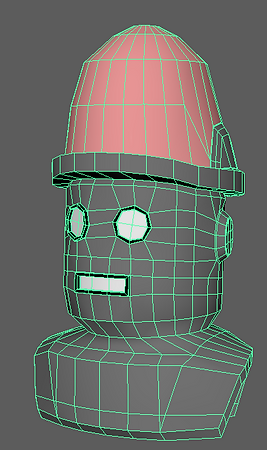
UV Mapping
What you're seeing is the latest version of the UV map and there's a lot to say.
I individually selected the shoulders, base head, ring and brain dome and scanned them with the cylindrical UV tool. I then stretched them out and placed them in order. The face, back, tip of dome, and bottom part of the helmet were done using a planar tool. Some parts were roughly connected with the rest of the UV shells, while the ones not relevant to the UV map were separated to a corner.
As for the 2 rings around the face, they were supposed to be the top and bottom parts of the ring inbetween the dome and head. They weren't properly unfolded, showing stretched textures on render, and there wasn't any luck to get them sorted whilst staying on the ring shell. As a last resort, I used a Planar tool to get them as regular rings and carefully position them near the face to take the textures from that side.
The bigger number of polygons is explained in the next section.

Colours, Bevel and Smooth
Before adding more polygons, Idecided to paint specific areas in a basic colour for later. The material would end up being the AiStandardSurface which is common in Arnold rendering.
Using the bevel tool, I wanted to smooth out sharp edges of the helmet like the eyes, mouth, ring and edges of the shoulders. The mouth was the trickiest since the insides made a more circular appearance when smoothed out. So I only did the outside parts.
When I felt that the model looked fine in the smooth preview (Shotcut key '3') I used the smooth tool on 1 to smooth out the model before porting it over to Substance Painter. I exported the model as an FBX and now moved onto the texturing phase.

.png)
Substance Painter
Using my action figure head as reference yet again, I gathered the needed infromation to determine the colours and textures of the model. To break it down, there were 4 textures. The ones I'll briefly mention would be the black outline and inside of the mouths. The black outlines were done swiftly with a painted metal prefab, while the insides will be applied with an Arnold chrome prefab.
The brain dome uses an opacity level for demonstration purposes so I can see what the model looks like when it's translucent. In addition, I changed the shader to one that had alpha properties and used that to apply an opacity bar to the texture. So then, I added a Glass Visor prefab, tewaked the colour to pink and used the paint tool to paint blue veins on the dome. Similar to the ones on the figure's head.
The base metal of the helmet was made using the grainy metal prefab. It was darkened slightly and whilst baking the whole model, I even applied a dirt generator to make the model more dirty. This layer would house the Normal mapping aspect to the model. I've used only one stamp prefab and that was a circle made up of dots. I edited it to have a reasonable amount of dots and coloured them black, and pressed them onto the models to both cheeks. Finally, I manually drawn the 2 lines on both sides of the helmet whilst again, using the action figure's head as reference.
.png)
.png)
Importing and Skybox
After the textures have been all set, I've imported them into the materials. Some of them didn't need the metalness, roughness or normal mapping due to being either blank spaces that add nothing or break the texture and leave with either a plasticy feeling or not being able to be translucent. I've tweaked the Normal mapping slightly since in my previous assignments, I've had horrid luck with black sides manifesting in normal mapping. Additionally, I've used the Transmission settings on the dome's textures to create the translucency on it's own.
The skybox was downloaded online from HDRI Haven and is of an indoor studio. It has its own lights coming from the sides of the room.

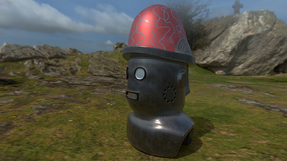
Arnold Renders
After all that, I've finally completed the model and it's ready to be rendered by Arnold. This process isn't that technical as it only needed time and a lot of my CPU memory. While on that topic, I wasn't able to insert a light source into the dome to shine out and the translucent effect is hard to notice due to the reflections.
Either way, I've done 6 renders and they're all ready for show.


Bonus
Since I've had the time, I also rendered the same textures in IRay in Substance Painter for demonstrations. This doesn't reflect the final product since it still has that stretched-texture-on-ring issue, but it's to show what it looks like in SP.